this video will show you how to create a reusable pattern in xGenerative Design
that will be an input to an action in the rich client
that will instantiate adaptive Engineering Templates
we'll start by making a new building product in the rich client
we'll give this product a name
and then we'll insert a 3D Part
this is going to be driving part for the project so we'll call it Driver
delete the instance name
and rename the 3D Shape inside that part
double click on the 3D Shape and we'll begin modeling
we're going to use the Imagine and Shape application to create a sub-division surface
this sub-division surface will be a base for a pattern in xGenerative Design
we'll scale this surface to approximatly 4 by 10 meters
rotate it
and now we divide this surface so that we can deform it slightly
to be sure that when we create the pattern in xGenerative Design
it behaves correctly regardless of the surface geometry
within the tools palet we can select different controlers to manipulate the Imagine and Shape surface
we'll commit those changes
and save our part
the save here is going to save the product structure and the part that we have created
in xGenerative Design now, we'll search for a recent content
drag the results into our xGenerative Design widget
and begin modeling by creating a UV point grid on the surface
and then we're going to maniupulate the lists that are output from the UV grid into triangles
so first we'll select our surface,
go to the Create tab
and make an offset of that surface
this is going to reference our surface into the graph
so that we can continue working with the sub division surface as an input
now we'll select the grid UV node
and we'll change the U and V sub division values
to 3 and 4 and extract them
so they are accessible later from the parameter set in the rich client
we'll give each of these a new name
the U and the V
and we'll connect our sub-division surface
here are the output points
from this grid, we are going to retreive the 4 vertices of each square
we call them A B C and D
first we need to remove the last row
and then the last column
in order to get point A
we'll do this by using the Remove Last node
of the first and then the second dimension
so back in the graph
we'll make a remove last node,
and we'll connect our UV node to the Remove Last
and in the first dimension you see what's removed:
the last point in each list
next we'll make another Remove Last node
this time we'll do it at the second dimension
and this is going to remove the last list
from that list of lists
this is going to be our A set of points
next, to get the B set of points
we are going to do a Remove Last at the first dimension
and a remove first in the second dimension
we can do the same for C and D
so we make a Remove First node
we set it to the second dimension
and we make a Remove Last as the input
next we'll do a Remove First at the first dimension
a Remove First at the second dimension
make a connection
so this last node creates the C points and we can check it
rename the node accodingly
and finally add a Remove Last node to create the D points
with dimension 2 set on the input structure
then we use a Build List node to construct the list containing A, B C and D points
rearrange the graph layout
and group the nodes together
to build the triangles in this first direction of cut
we need to extract list of points ABC
by removing the 4th item D
this is what we are doing now with the Remove Index node
we set the index to 4 and check that it gives the expected output structure
in the same maner, removing the second item of the ABCD list
will create the list of ACD points
needed to create the second triangle in this direction of cut
a duplication of the previous node with the connection is an easy way to reproduce the operation
but this time on index 2
and we check again that we get the expected lists of points to create the ACD triangles
to build list of Points ABD and BCD
remove item 3 and item 1 of the ABCD list
since we want to control the direction of cut, let's create a mechanism with a selector to remove either items (4 and 2) or (1 and 3)
let's create the 4 integer values 4, 2, 1 and 3
create two lists from these values
the first one with 4 and 2, and the second one with 1 and 3
the node called selector will be used to extract the values from one list or the other
based on a integer input, displayed with a slider
and visible under the parameter set on the rich client
playing with this parameter, the node extracts either the first item or the second item of both lists in entry
and use get item to retreive first and second item on the input list
check the result they return as we change the direction of cut parameter
and connect these outputs to extract triangles from the ABCD list
the mix node is to merge the 2 lists into one
then build the triangles from the list of points using a Polyline
hide the surface to better see the effect of the Direction Of Cut parameter on the computation
from now we compute the geometrical elements needed as input for the Engineering Templates
create the center of gravity
and the surface of every triangle
build a line normal to that surface
and extract the orientation parameter
then create the axis system for every triangle
with Z axis in the normal direction
in addition to the axis systems
the templates need the 3 summits of every triangle
the Sub Elements node retreives the points from the polyline
and Get Items on index 1 gives the list of first point of every triangle
repeat this node with index 2 and 3 to get the list of second and third point
check the content of every list and make sure the points are oriented clockwise around Z axis on every triangle
as this is a specification of the Engineering Template inputs
if it wasn't the case we would wimply need to invert the direction of the normal line
to change the orientation of the axes
to get these geometries available on the rich client side we need to publish it with Publish node
each of these node will create Geometrical Sets containing parametric geometry available for further processing
you don't need to publish axis systems as they are natively available on the rich client side
rename the Publish nodes to get the proper names on the Geometrical Sets
publish also the triangle surface although they are not needed as input for the Engineering Template
back on the rich client side,
reopen the building product structure with the driver part modified in x Generative Design
under the Parameters node you find the driving parameters
that you can change to modify the number of panels
or the direction of cut to recompute the triangles
you can also modify the Imagine and Shape surface and recompute the triangles
insert the replicator part that contains the action able to automate the generation of detailed panel
this part is the result of the tutorial called "Automate generation of sub assemblies in a Product Structure"
that you will find on the CATIA AEC YouTube channel
run the action, select inputs in the drivers part, and validate
after a while you get all the detailed panels generated,
every panel is composed of a unique plate and 6 fixings all identical
the detailing is parametric and you can modify the direction of cut
and update the definition of each detailed panel assembly
if the original surface needs to be changed for another one, it's possible to update the model using a new surface reference
as the modification doesn't change the number of panels, the update will only take few seconds


 For more infomation >> Why You'll Never Find the Right Person - Duration: 3:57.
  For more infomation >> 58+ Landscaping Pool Best Decking ideas | Garden Ideas - Duration: 11:30.

 For more infomation >> O GRANDE SEGREDO DA MULHER MARAVILHA - Duration: 7:24.
  For more infomation >> ¡Nació el hijo de Fabián Ríos y tenemos imágenes! | Un Nuevo Día | Telemundo - Duration: 2:28.
  For more infomation >> Emma Coronel causa sensación por fotografía ¿con su sensual hermana? - Duration: 3:27.
  For more infomation >> Мой Говорящий Том 2 НОВАЯ ИГРА #35 Друзья Анджела Хомяк My Talking Tom 2 Игровой мультик для детей - Duration: 20:11.
  For more infomation >> Using Layouts Part 6 | How to resize, align and constrain a view in ConstraintLayout - Duration: 6:54.

 For more infomation >> Como surge o endividamento crônico? - Duration: 1:19.
 For more infomation >> LOVE!!ネコだらけの猫村【台湾ひとり旅】台北 猴硐 in Taipei Episode14 - Duration: 6:18.
 For more infomation >> 廖峻驚傳中風⋯澎澎淚揭原因 家屬12字曝光病況 - Duration: 2:58.
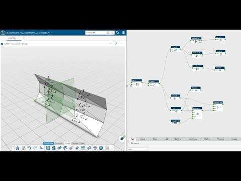
Không có nhận xét nào:
Đăng nhận xét